General AI models enter hardware development, from files to prototypes
Youxin reviews hardware-design examples involving OpenAI, Anthropic and engineering tools, spanning circuits, enclosures, firmware and CAD. Some prototypes were built and tested, but digital checks, engineering review and physical reliability remain distinct hurdles.
"Scientists discover the world that exists; engineers create the world that never was." — Theodore von Kármán
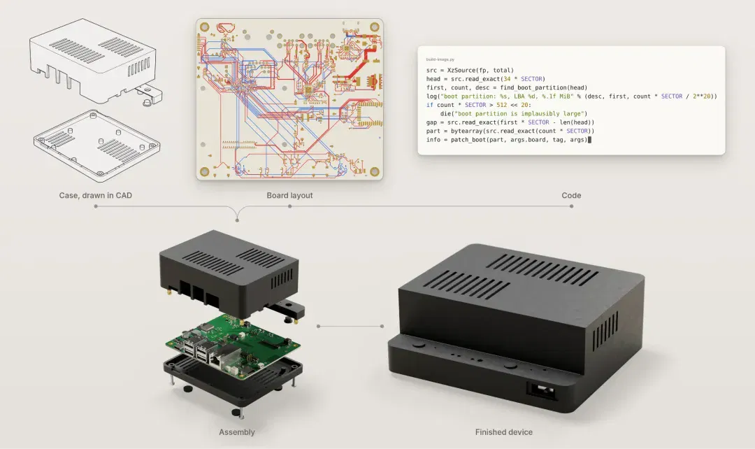
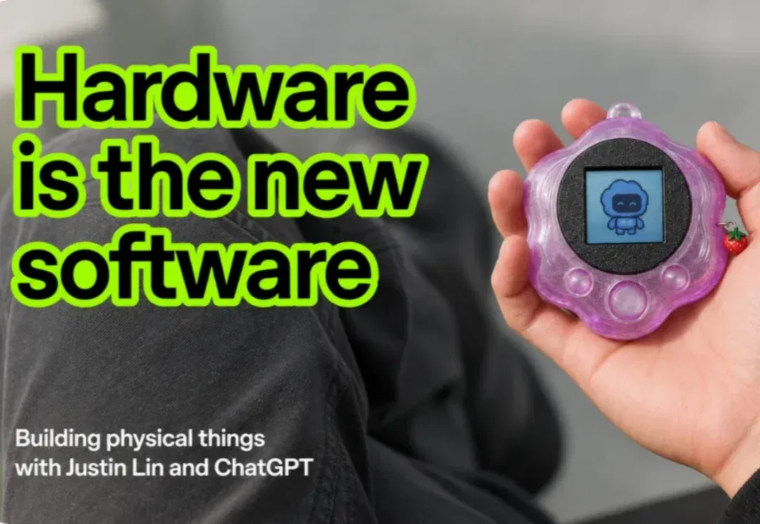
In early November, OpenAI publicly demonstrated progress in using general-purpose models for hardware development. In a project announced on November 3, GPT-6 Astra helped design a device that could converse with Codex, covering its enclosure and internal structure, circuit-board layout and firmware. OpenAI also described a collaborative effort to turn 3D scans of parts into editable CAD models and 2D manufacturing drawings.
Two employees worked on the device in their spare time, completing the design in less than a week. A contract manufacturer then produced a small batch of prototypes in under a month. However, OpenAI also noted that the design still needed multiple rounds of review and adjustment before being sent to the factory. The model's grasp of manufacturing conditions, dimensional tolerances and assembly requirements was not yet sufficiently reliable.
Less than a week later, Anthropic and circuit-board design and manufacturing company Diode announced another set of advances. With a small number of human prompts, Fable 5.2 designed the circuits, enclosures and firmware for three electronic devices. Diode engineers then manufactured, assembled and tested them from those files, without needing to correct the circuitry in any of the three devices. These working prototypes offered a concrete demonstration of the model's ability to handle manufacturing and assembly constraints.
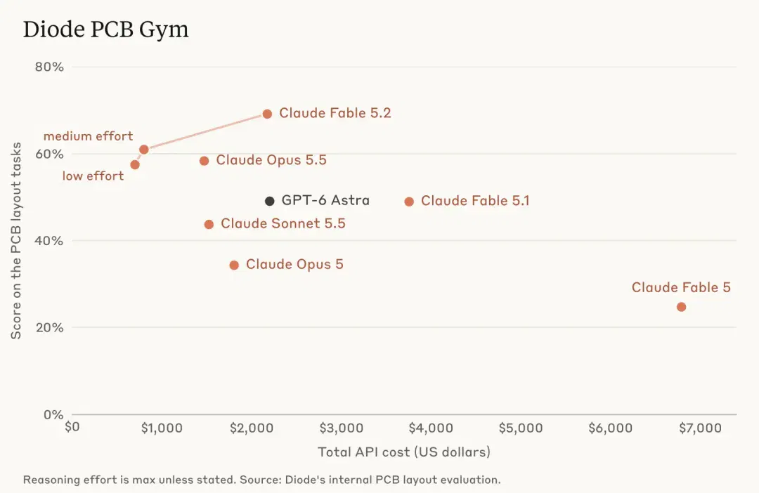
These results indicate that Fable 5.2 can now undertake a continuous workflow from requirements to the complete design of an electronic prototype. When Anthropic tested a model with Diode more than a year earlier, it still struggled to lay out circuit boards consistently and often produced parts that would not fit together. This time, a small number of human prompts enabled the model to connect designs across several disciplines and ultimately hand engineers something they could physically build.
Similar design experiments are beginning to appear in users' own projects. In November, a user on X gave Claude Fable 5.2 an engineering problem he had already worked on: designing a relatively high-current boost-converter board. He had spent weeks refining his own design and wanted to see how far the model could get with the same requirements.
He listed protection and control requirements in Diode's tools and asked the model to handle component placement and routing. A boost converter raises a lower voltage to a higher one. Beyond connecting traces, its design must properly arrange high-current paths and protections against overcurrent, undervoltage and overvoltage. Some of the model's design choices were quite similar to those in his manually developed design.
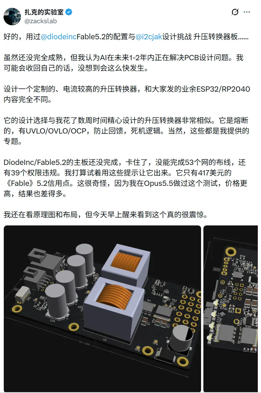
Initially, the model still had 53 unrouted connections and 39 clearance issues, having already used approximately $417 in credits. He later posted an update on X: after he had been away for a full day, the model had continued working and fixed the routing, clearances and silkscreen.
From specifying requirements to revising the layout, the project demonstrated the model's ability to continue developing a design after receiving feedback. The three official prototypes took that work further into manufacturing and assembly, testing the circuits, mechanical structure and firmware in the same physical device. Model capabilities in hardware development are beginning to yield concrete results that can be powered on and run.
▍Three working prototypes complete the handoff
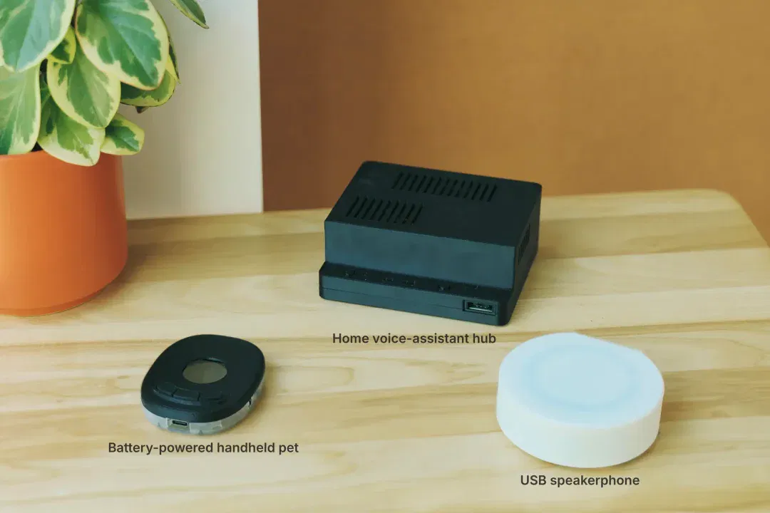
The designs for all three prototypes began with brief product requirements. Anthropic asked Fable 5.2 to design a conference speakerphone, a home voice-assistant hub and a handheld digital pet. For the speakerphone, the initial requirements called for a USB-C connection to a computer, a microphone and speaker, and Bluetooth support. Fable 5.2 used these to organize specifications, select components, design the circuit and route a four-layer board, then generate the enclosure, firmware and bill of materials. Diode engineers assembled it and ran the firmware. Anthropic reported that the prototype still worked after several weeks of use.
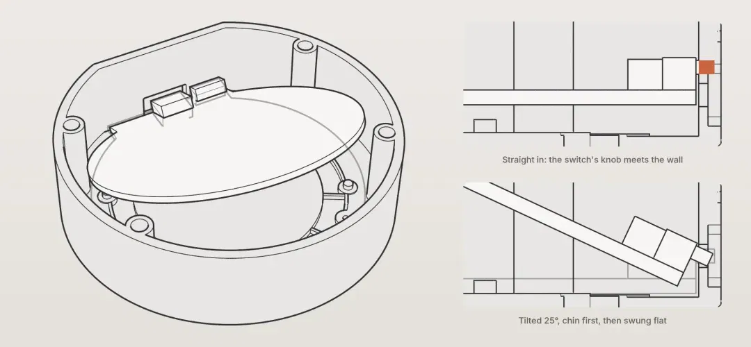
The design process also surfaced details requiring consideration across disciplines. If the speakerphone's board were placed straight into its enclosure, the switch would get in the way. After checking the 3D model, the model changed the installation method: tilt the board by approximately 25 degrees, then lower it flat. It included this procedure in the assembly instructions.
The voice-assistant hub presented a different problem: routing the long traces to its connectors individually was too cumbersome. The model spent about half an hour writing a routing algorithm that divided the board into a grid and searched for paths, completing each long trace in about a second. After noticing that the audio clock line was close to Ethernet traces, it adjusted the algorithm to leave more space around sensitive signals.
As it prepared to send the design for manufacturing, the model also checked the board manufacturer's fabrication requirements and component availability. Six areas of solder mask on the voice-assistant hub were too thin. It resolved the issue by enlarging the openings without moving any components. According to Anthropic, Diode manufactured the three boards directly from the model's files, with no back-and-forth revisions to the fabrication files. Handling these details allowed the designs to proceed to actual manufacturing.
From rerouting traces to adjusting the installation angle, Fable 5.2 had to carry forward a series of design decisions within the same device. It first checked the fit between the board and enclosure in the 3D model, then documented the installation method in the assembly instructions. The design handed to engineers explained how the electrical and mechanical elements fitted together and how to assemble the device, providing a corresponding basis for the physical build.
Beyond the assembly sequence, there was also room to improve the circuit layout. In comparing the boost-converter boards, the user mentioned earlier still considered his own design to have greater power density: it could handle more power within a similar volume. Because both designs followed the same requirements, component placement and use of board area had a common reference, allowing engineers to continue comparing layouts and refining the designs.
In mechanical design, another X user tried asking Fable 5.2 to design a humanoid robot. Overnight, the model generated build123d CAD files, a MuJoCo simulation and a Blender demonstration video, linking structural modeling, motion simulation and visual presentation into one workflow.
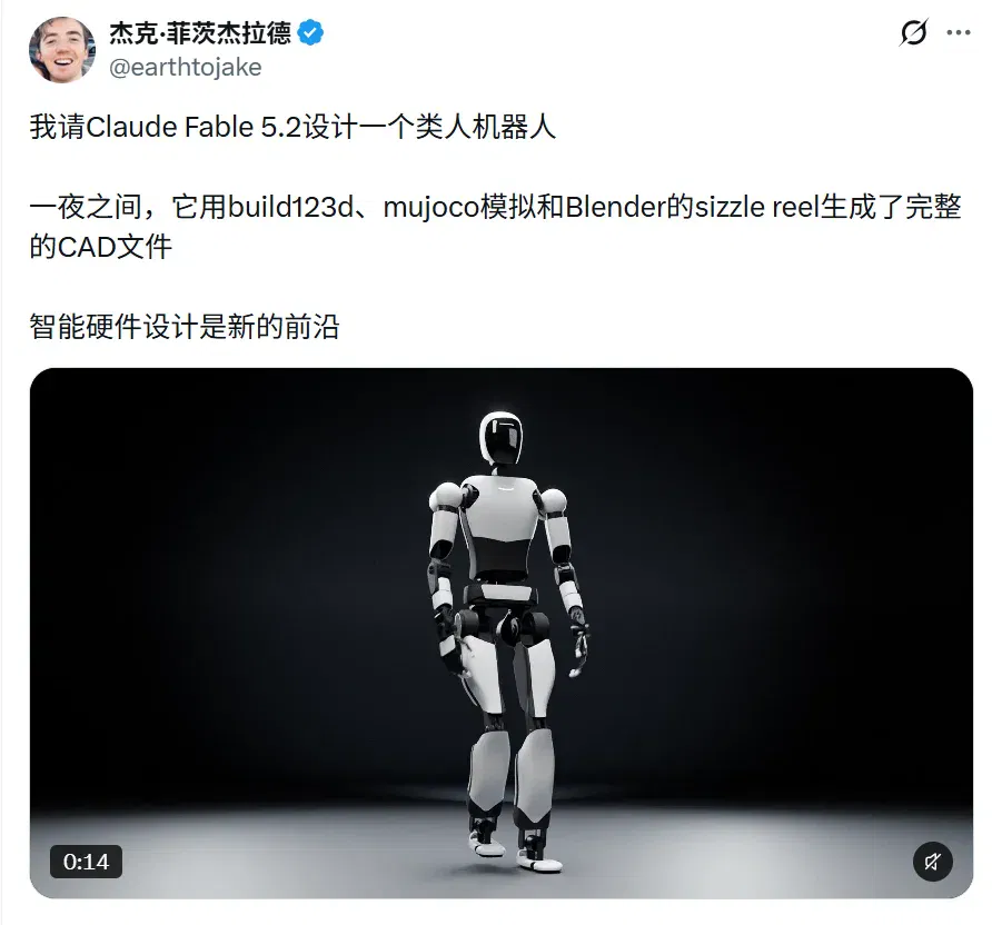
Digital designs of this kind give teams proposals they can inspect and modify. They can discuss component positions, mechanical fit and movement before proceeding to part selection and prototyping. The electronic prototypes have demonstrated one path from design to physical hardware; the mechanical models extend the model's role in development into structural and motion concepts.
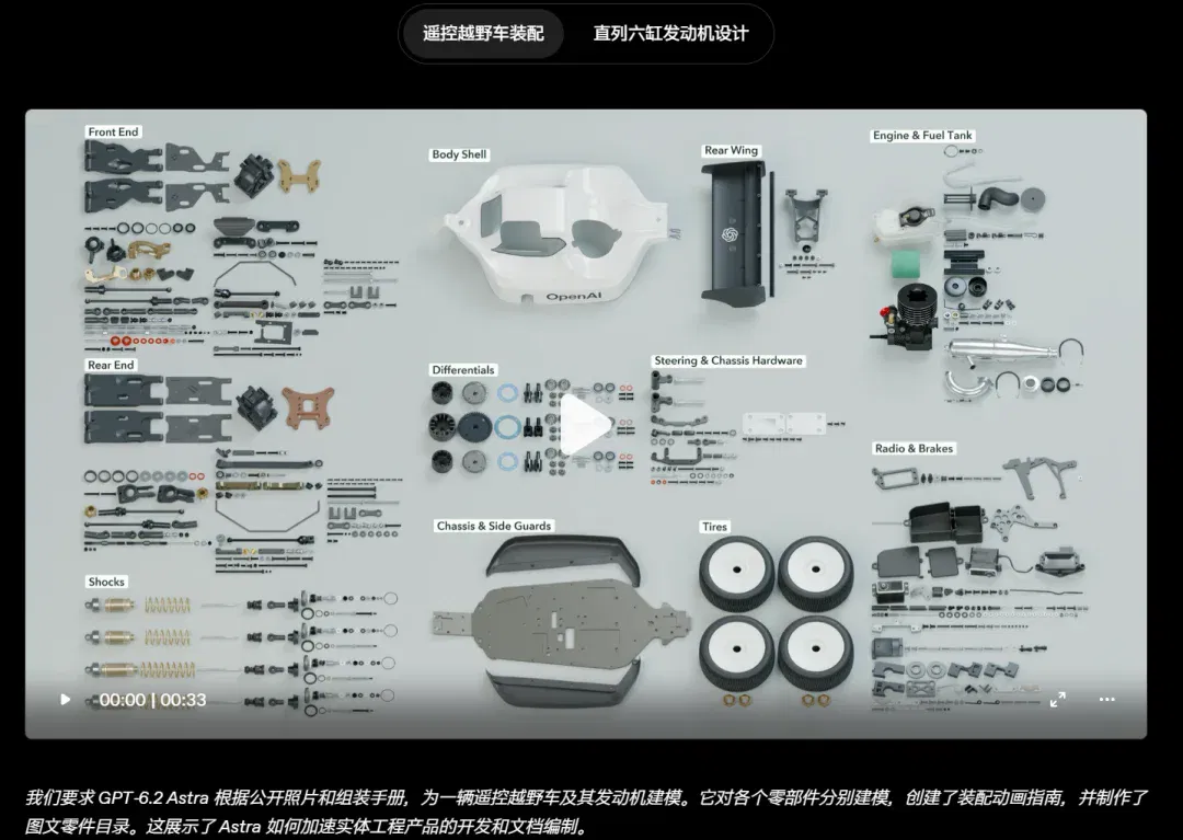
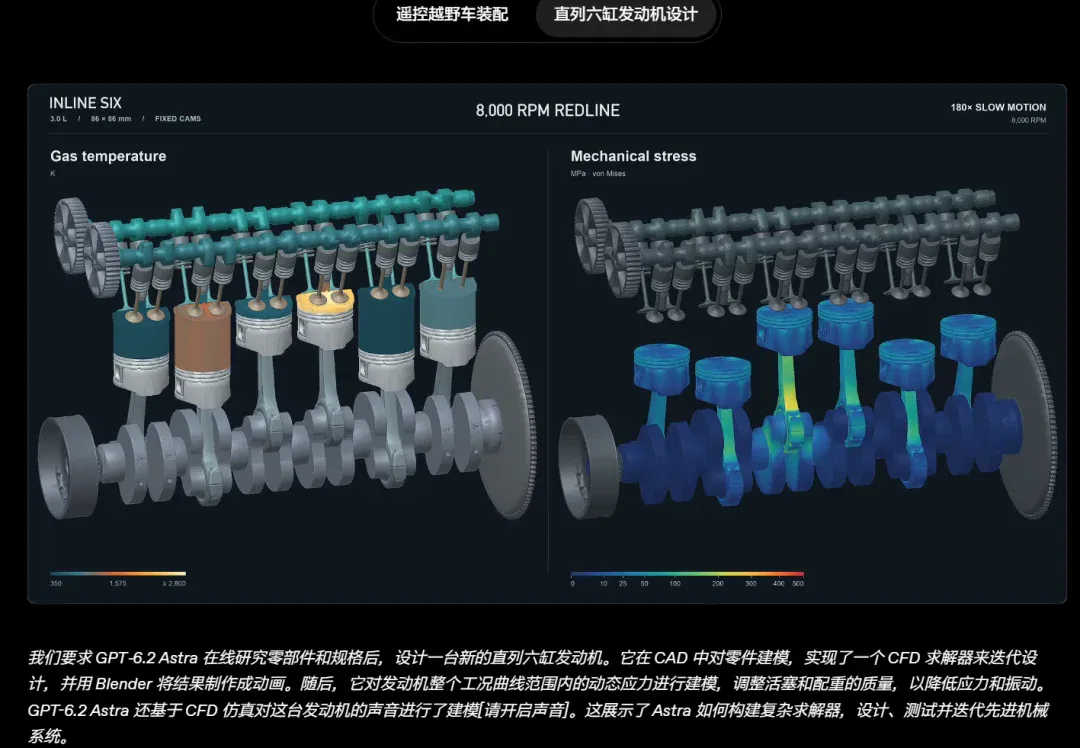
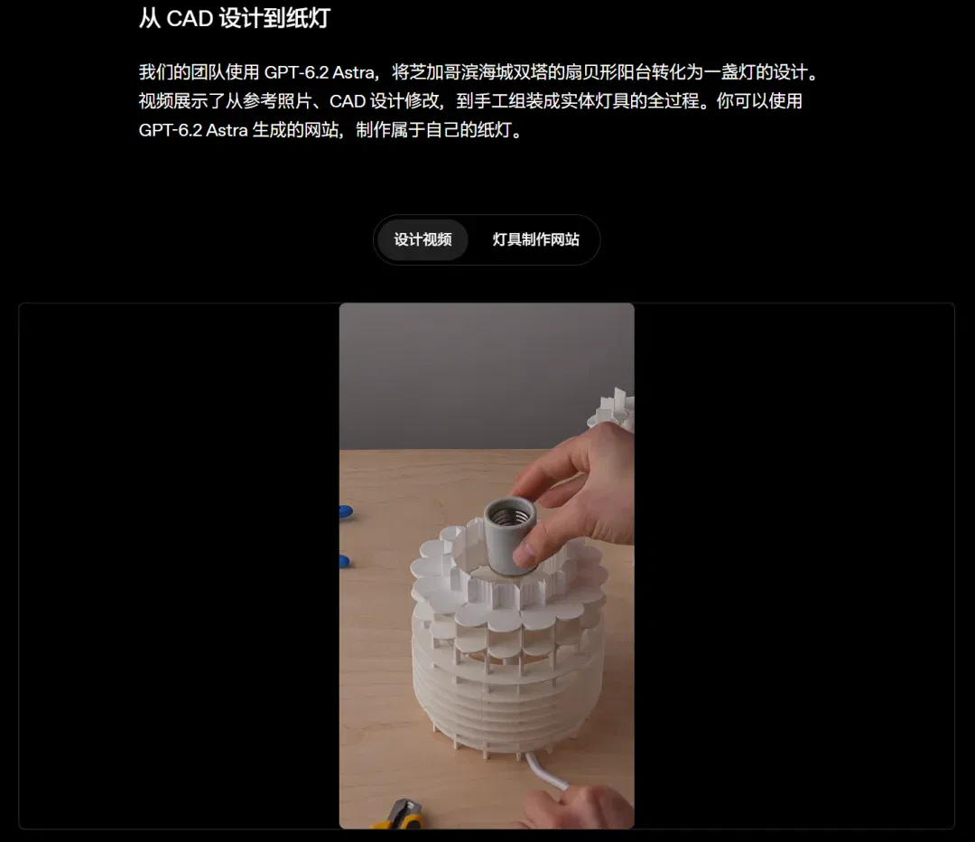
The newly released GPT-6.2 Sol and GPT-6.2 Astra can already produce hardware-design files for engineers to review. In an OpenAI demonstration, Astra reconstructed a radio-controlled off-road vehicle and its engine part by part from public photographs and manuals, generating an assembly animation and a parts catalog. In another demonstration, the team manually assembled a paper lamp from a CAD design modified by Astra. In six trial board-design tasks on PCBBench, two of Sol's designs passed digital checks, while the other four failed bill-of-materials verification. On one board, the schematic specified 5.1 kilohms, but the selected resistor part number corresponded to 510 ohms. Engineers receiving these files can check them against the assembly steps and component lists before deciding whether the designs are ready for prototyping.
▍AI takes up the hardware engineer's toolbox
Connecting models with engineering software is essential if a design is to be handed to engineers for manufacturing. Diode provides tools for electronic-device design, while the robot example links CAD, simulation and rendering software. The open-source software Backplane brings circuit and mechanical-model operations into a single workbench, helping agents apply their changes to engineering files.
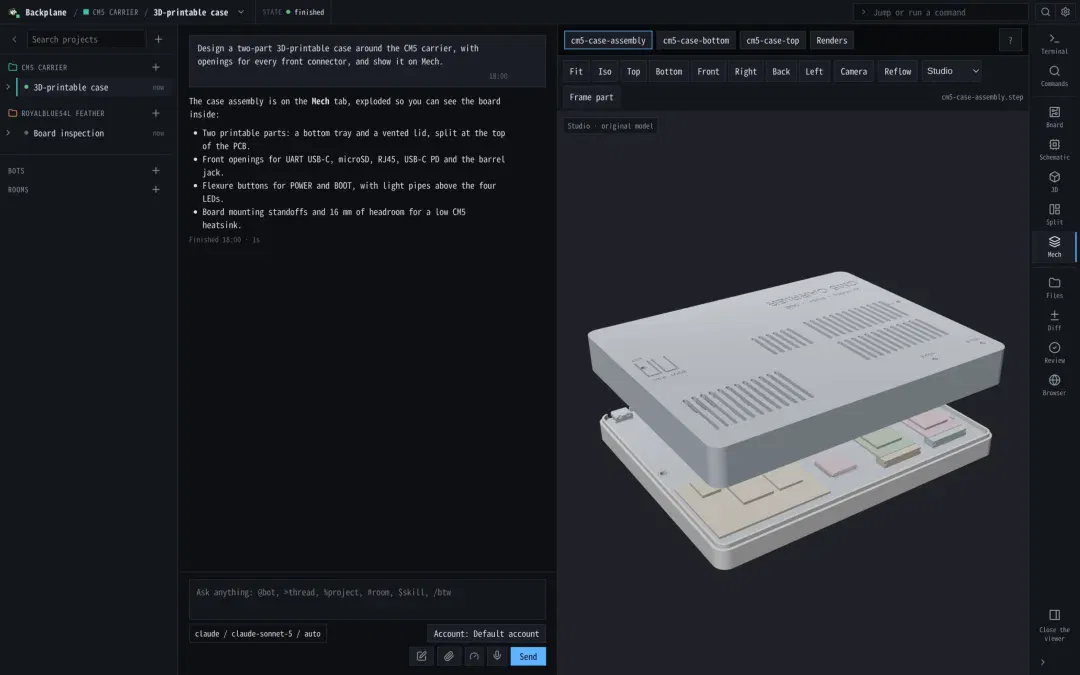
Backplane is open-source hardware-development software for agents, connecting KiCad for circuit-board design with FreeCAD for mechanical design. Users can choose agent tools such as Claude and follow the design's progress in a single interface. The board, schematic and 3D model are displayed separately, making it easier to inspect the parts the model has just changed.
Backplane adds a software communication interface to KiCad, through which agents modify boards and schematics. The software saves each round of changes. Engineers compare earlier and later versions to inspect the design, then annotate the locations that need revision with their review comments.
These records become useful when taking over an AI-generated power board. Engineers can see which component the model replaced and which connections it changed before deciding what to keep or revise further. Changes to the power circuitry can also be reviewed alongside enclosure dimensions and connector positions. After the model completes a round of work, the team can continue from the current files and send its review comments back to the agent.
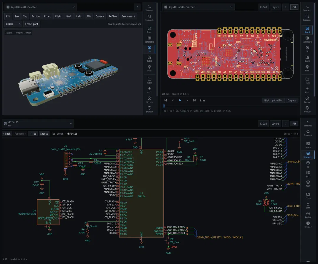
The change history also connects to Backplane's design-review function. The software first checks trace clearances, electrical rules, materials and factory constraints, then asks the agent to verify symbols and footprints against component datasheets. For example, a rules program calculates trace clearances individually, while pin-to-pad correspondence is assessed using the design files and datasheets together. The model's judgments include document page numbers and confidence levels, allowing engineers to trace their basis and pass the findings back to the agent for further revision.
After the agent revises a design in response to the review, those changes still need to appear in the fabrication files. During a full review or an order review, Backplane re-exports manufacturing files from the saved board, compares them with the existing output and marks checks that have not yet been completed. Changes to traces, board outlines and drill holes are thus included in the checks before sending files to the factory, helping the team confirm that the files used for subsequent manufacturing match the current design.
▍Bringing parts out of the drawing
Behind these software operations lies the model's understanding of engineering drawings and spatial relationships. BenchCAD breaks some of these capabilities into tasks: building parts from drawings, assembling parts in the correct positions and reconstructing connectivity from circuit-board images. The model must produce executable geometry or connectivity results, which a program then compares with reference answers.
In the standard BenchCAD 2.1 test environment, Fable 5.2 scored 0.754 at its highest reasoning setting, compared with 0.363 for the previous-generation Fable 5.1. On the same benchmark version, using the same tool and highest reasoning setting, GPT-6.2 Sol scored 0.731, up from its predecessor's 0.526. Both generations cost $1.60 per case.
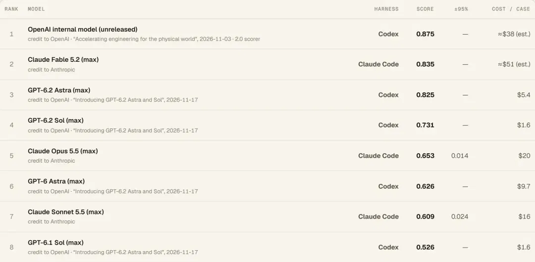
These tasks correspond to preparatory work in hardware development. Given a dimensioned drawing, a team can ask the model to build the part first and check the installation space. With an existing set of parts, it can ask the model to attempt assembly and expose positioning and fit problems. Understanding connectivity can help interpret existing boards and organize information in images into structures that can be processed later.
Designing a complete device requires a clear installation path for every part. The angle at which a circuit board can enter an enclosure depends on how much room the enclosure leaves it to rotate. Fable 5.2 checked the installation path in the 3D model, then wrote specific steps in the assembly instructions for engineers building the prototype.
▍New possibilities opened by prototype delivery
The three devices represent a complete handoff within the prototype-development stage. The enclosure CAD, board layouts and code submitted by the model ultimately corresponded to assembled devices. Diode handled procurement, board fabrication and assembly, after which engineers tested the designs with physical hardware. With working prototypes in hand, the team could move the discussion from proposals in files to actual performance.
For hardware teams in China, limited revisions to existing boards offer a relatively near-term entry point, such as changing a power module or replacing a connector. Established projects already have dimensional, performance and interface requirements. Models can use these to generate revision files, which engineers review before proceeding to prototyping. The design, inspection and debugging records left by each round can also serve as references for the team's next revision.
Teams pursuing these revisions need to account for the combined investment in model calls, human review, board fabrication and assembly, debugging and rework. Incorporating component availability and board-manufacturing requirements early in the design can also help reduce extra costs from later component substitutions and board revisions. This allows teams to compare the full investment required to obtain a testable prototype.
Fable 5.2 has now added another way to advance hardware design. Anthropic next plans to have the model handle denser, faster and more complex circuit boards, connect to simulation and learn from measurements of finished devices. As design, manufacturing and measurement become connected, models may be able to use physical feedback to continue improving layouts, structures and firmware.
As this collaboration develops, projects such as industrial sensors, equipment control boards and specialized test fixtures may also use general-purpose models to shorten the path from requirements to prototypes. Models work across circuits, structures and firmware, bringing constraints from different disciplines into the same proposal earlier, while engineers make judgments about performance and reliability. The three small electronic prototypes provide a concrete starting point for this development approach. More complex industrial hardware offers a promising area of application for the next stage.
This article was originally published by Youxin Newin. Author: Youxin.
Related topics
After reading
Join the AINRK community
Read how to join the community and connect with people working in AI.
Related articles
Continue reading related topics and articles in this category.
Suisheng raises tens of millions of yuan for Memoket wearable AI memory (opens in a new tab)
Zhidx interviews Suisheng founder Wang Shiyuan about the Memoket Gem wristband, KITE long-memory engine and software subscriptions. Funding, battery life, early user results and benchmark figures are company statements; long-term use remains to be tested.
Turning an unused Android handheld into an AI terminal with buttons, NAS memory and home control (opens in a new tab)
The author rebuilds a handheld around a Big Fat Fish character, voice input, meeting archives and Mijia controls. The project also exposes audio conflicts, button noise, clipped speech and excessive token use from camera polling.
How long is the window for AI recording hardware? From audio capture and transcription to personal-agent context (opens in a new tab)
GeekPark examines watches, recording cards and wearables, discussing system access, memory filtering and interface integration. Its six-month window is the author's forecast of competition.

iQIBLA opens Aura Premium preorders, bringing recitation counting and records to a ring (opens in a new tab)
The ring combines touch counting, display prompts and prayer reminders with app-based recitation records. The four million sales mentioned in the report refer to cumulative sales of the brand’s products.
OpenAI 工程案例用 GPT-6 Astra 设计 Codex 掌机原型 (opens in a new tab)
OpenAI 两名员工用 GPT-6 Astra 设计掌机外壳、电路与固件,再经人工审查和制造修改,完成小批量原型。报告还分享了赛车零件与汽车仿真案例。